
Electric heat
History of Electric Heat
The growth of electric heating began in the 1950s and first became popular in areas not served by natural gas pipelines. Throughout this same period, the electrical demand for air conditioning during the summer months was increasing. To help boost the winter demand, electric utilities and heating manufacturers began to encourage the use of electric heating. One widely used application was as a baseboard heater.
Today, many systems provide both heating and cooling with a single air distribution system. Therefore, most air handlers are configured to accept both cooling coils and heating elements. This has reduced the number of installations for straight stand-alone electric furnaces, and instead, electric heat is often used in combination with a cooling system or a heat pump.
Warm Air Electric Furnaces
The typical residential electric furnace consists of a cabinet, blower compartment, filter, and resistance heating section. Most manufacturers provide a place for a cooling coil.
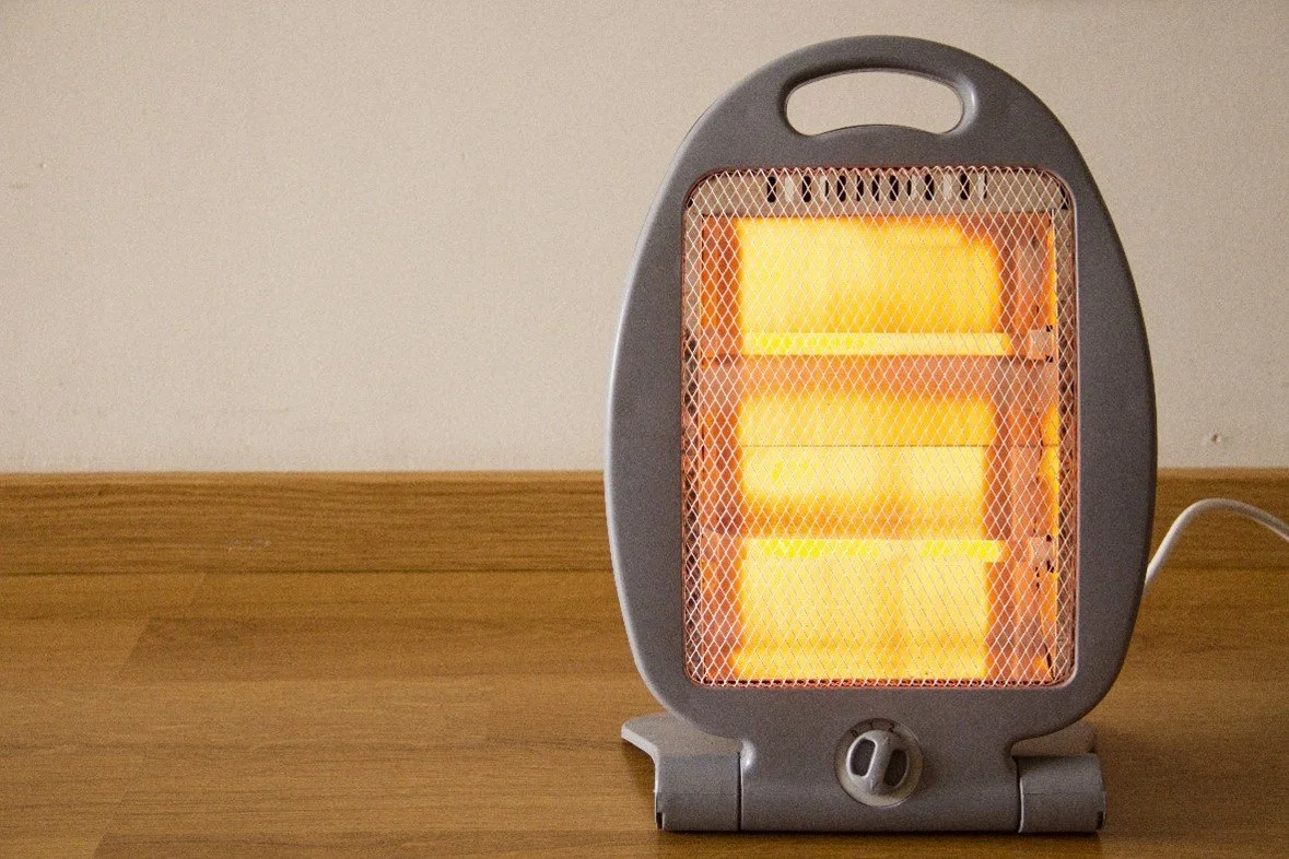
Electric Heater
Advantages of Electric Heat
Electric heat has many advantages:
It is more compact than the equivalent natural gas or oil furnace.
Due to cooler surface temperature, it has "zero" clearance requirements on all sides. It may, therefore, be located in small spaces, such as closets.
Since there is no combustion process, there are no requirements for venting pipes, chimneys, or makeup air. This reduces building costs and simplifies installation.
Units may be mounted for upflow, downflow, or horizontal airflow applications.
With electric heat, there are no losses such as those experienced with oil and gas combustion processes. Therefore, electric heat is considered to be close to 100 percent efficient.
Components of electric furnaces
The blower compartment is a housing that includes the filters and the blower fan for circulating the air through the system. An electric furnace has less resistance to airflow as compared to an oil or gas furnace, and fan performance is efficient.
The heating section consists of banks of electric resistance heaters made of nickel chrome wire held in place by ceramic insulators.
Calculating the heating capacity of an electric heating system
One watt of power produces an equivalent of 3.412 BTU/hr of resistant heat. Electric power is measured in kilowatts (kW), with 1 kW being equal to 1,000 W. The term kilowatt-hour (kWh) is used to express the amount of energy used in 1 hour. The input for an electric furnace is given in kWh, and the output is given in BTU/hr. To find the heat output in BTU/hr, multiply the kW input by 3,412. Conversely, the input kW can be calculated by dividing to furnace BTU/hr output by 3,412.
The amount of heat produced by an electric furnace is a function of the supply voltage and the current flow.
Watts = Volts X Amps
A furnace rated at 240 V with a current draw of 125 A would have a kW input of 240 V x 125 A = 30,000 W, which is 30 kW. Residential furnace output capacities normally range from 5 kW (17,060 BTU/hr) to 30 kW (102,360 BTU/hr).
Sequencers
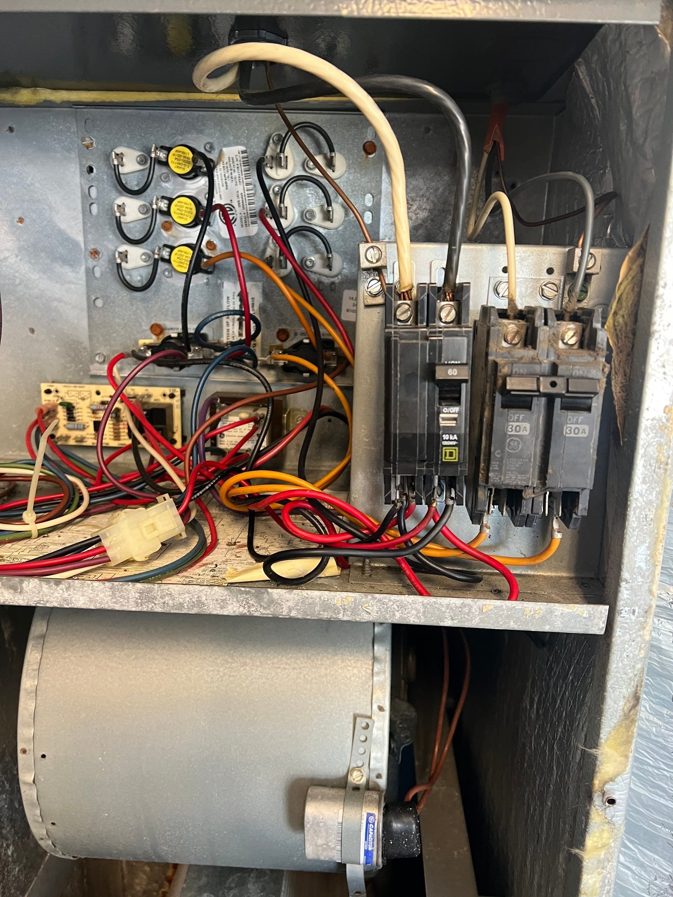
The basic operation of a heating sequencer
The sequencer control is an important operation of the electric furnace. When there is a call for heat, the electric sequencer contacts close, and the circuit is energized. As the sequencer begins to heat up, the blower and first heater come on. To stage the elements, there is a time delay (in seconds) before each additional heater stage is energized.
Electric furnaces that have multiple heat strips are designed with a sequencer that allows each heat strip to come on individually or in small groups. Most systems use sequencers to sequence or stage elements.
Construction and design of heating sequencers
A sequencer uses a small heating element wrapped around a bimetal strip or a PTC control. When the bimetal strip warms up enough, it snaps or warps to close a set of contacts to turn a heat strip on. Some sequencers have multiple contacts that are staged. Staging can be accomplished by using a center pin that pushes upward on each successive set of sequencer contacts. In some cases where several heating elements are sequenced to turn on, multiple sequencers are used.
Sequencer cycling
To prevent the heating elements from overheating, the unit blower must come on with the first heating element, and it must remain on throughout the heating cycle until the last-stage heating element has cycled off. Some sequencers have specific terminals that are designated for the blower. This set of contacts is the first on and the last off in the sequence.
The time interval between when a sequencer is energized and when its contacts close is predetermined, within a range, by the sequencer's manufacturer. Some manufacturers offer sequencers with different time cycles. Likewise, the time interval between when a sequencer is de-energized and when each of the contacts drops out is preset by the manufacturer. In some cases, although the sequencers may come on one at a time sequentially, they may all go off at the same time together.
Heating Elements
Construction of heater coils
The heating elements used in electric furnaces are made out of a nickel-chrome alloy. The nickel-chrome alloy is used because it has both high electrical resistance and slows down oxidation. Many metal alloys have an electrical resistance too low to be effective heating elements. Also, many alloys are susceptible to extreme oxidation at elevated temperatures. Heating elements appear to be long coil springs and are bright in color until the coil is heated.
As the elements are used, they will begin to discolor. Eventually, they will become dull black. The length of the heating element determines its kW capacity. Heating elements are available in 5 kW through 30 kW capacities for residential electric furnaces and may be as large as 60 kW or more for commercial electric furnaces.
Replacing heater elements
Electric heating elements are rated by their kW capacity and come in a prewired rack. Each electric furnace is designed to hold a specific type and size of heating element rack. These racks are not interchangeable from manufacturer to manufacturer, or in many cases from one model furnace to another within the same manufacturer's product line. When replacing a heating element rack, be sure that you specify the model and serial number of the furnace the rack is to fit into.
Some heating element racks can be restrung with a replacement heating element. An advantage to restringing heating elements is that only a limited number of heating element sizes need to be stocked in your service van. However, replacing the heating element rack results in significant time savings over restringing, and you are providing the customer with an entirely new part. Sometimes, the ceramic insulators can be damaged during restringing. A damaged insulator may fail sometime after the installation job is complete.
Applications for electric resistance heat
Supplementing heat pumps
One common application of an electric furnace is to combine it with a split-system electric heat pump. Whenever the outdoor temperature drops below the thermal balance point of the heating system, the heat pump alone may not be able to maintain a comfortable indoor temperature. This is when the electric furnace will supply the additional heat necessary to maintain the thermostat setpoint.
Installation arrangement
For these installations, the electric furnace acts as a fan coil unit. The refrigerated coil is installed in the furnace return-air stream before the blower. The coil is connected by refrigerant tubing to the outdoor heat pump located on a slab outside the building. The thermostat is located in the conditioned space and controls the operation of the complete system to produce the heating or cooling as required.
Energy conservation concerns
Because of energy conservation concerns, some cities, counties, and states have ordinances or laws that prevent straight stand-alone electric furnaces from being installed in new construction. This is because heat pumps are more efficient and under normal operating conditions will use less electricity. In those localities, heat pumps are used for primary heating in conjunction with electric furnaces that supply only supplemental heat.
Electric Furnace Controls

Thermostats
There are single two-stage thermostat systems, depending on the size of the unit. A fan control switch lever can be set to operate at low, medium, or high speed whenever the heating or cooling equipment cycles on.
Staged for energy efficiency
Larger furnaces and some heat pumps use multistage thermostats. For electric furnaces, the first stage would bring on at least 50 percent of the total capacity. The second stage of the thermostat would respond only when heating capacity is needed. With this added control, wide variations in indoor temperature are avoided. For heat pumps, the first stage brings on the heat pump, and the next stage brings on the electric strips as needed.
Thermostat settings
Two-stage heating and cooling switch settings to control the thermostat operation are as follows:
Off- Heating and cooling systems are off. If the fan switch is in the AUTO position, the cooling fan is also off.
Cool- The thermostat controls the cooling system. The heating system is off.
Aux. Heat- Auxiliary heat is on. The cooling system is off.
Heat Pump- First-stage heat is on. The cooling system is off.
2 Stg. Heat- First- and second-stage is on. The cool system is off.
Electric Furnace Air Distribution and Blowers
Air-handling capabilities of electric furnaces are similar to other forced-air furnaces, using a multispeed direct-drive blower. Multispeed direct-drive blowers can adjust the blower speed to deliver the required air quantity depending on the static resistance of the supply- and return air duct system.
Safety Devices
All electric resistance heating circuits have one or more safety devices to protect the system from overheating and overcurrent. Electric heating elements are protected from any overheating that may be caused by fan failure or a blocked filter. High-limit switches sense air temperature and open the electrical circuit when overheating occurs.
As a backup, some furnaces have fusible links that melt when the heating coil temperature goes too high due to overcurrent conditions. This opens and protects the circuit. A fusible link is a small one-time-use device that is wired in series with the heating element.
A high limit is another heat protector for electric heating elements. High limits sense temperature so that in a high-temperature situation the limit will open. High limits will automatically reset once the bimetal strip in the limit has cooled sufficiently.
Inline cartridge (BUSS) fuses are used to protect individual heating elements, groups of heating elements, or the entire furnace. Fast-acting fuses should be used instead of dual-element time-delay types. The metal clips that hold cartridge fuses in place have sufficient spring tension when they are new to prevent heating of the connection between the fuse and the fuse holder.
Circuit breakers may be used as overcurrent protection. Circuit breakers used on the 208 V to 240 V systems have two breakers that are interlocked so that overcurrent in one leg causes both breakers to open, removing power from the load.
Conclusion
In conclusion, the HVAC air distribution system stands as a linchpin in creating an optimal indoor environment, seamlessly blending comfort and health. Its significance extends far beyond merely regulating temperatures within homes equipped with air conditioning systems; it is the conduit through which conditioned air reaches every corner of a living space.
Beyond the realm of temperature control, the influence of air distribution permeates the sphere of indoor air quality. By facilitating the delivery of clean air and efficiently managing humidity levels, a well-conceived air distribution system becomes a stalwart guardian against pollutants, allergens, and unwanted odors. It thus becomes a silent champion in fostering a living space that is not only comfortable but also inherently healthier.
Comprehending the intricacies of HVAC systems, from the essential components like the air handler, heat exchanger, and condenser to the intricate ductwork systems, is pivotal in understanding how these systems synergize to create an environment of thermal comfort and superior air quality. The diverse range of HVAC systems, encompassing air-source, ground-source, and water-source heat pumps, adds a layer of adaptability to meet the varied demands of different climates and energy efficiency benchmarks.
The selection of duct construction materials, ranging from sheet metal to aluminum, duct board, and insulated flexible ducts, reflects the nuanced considerations of strength, insulation, and cost-effectiveness. Similarly, the choice of duct shapes—round, square, rectangular, or oval—becomes a pivotal factor influencing both efficiency and ease of installation.
The integration of fresh air intake emerges as a strategic imperative in ensuring a constant supply of oxygen while preventing the accumulation of indoor pollutants. Whether achieved through controlled fresh air ducts, motorized dampers, or the utilization of heat recovery ventilators, modern HVAC systems contribute significantly to sustaining indoor air quality.
Ultimately, a meticulously designed and diligently maintained HVAC air distribution system transcends its functional role—it becomes a catalyst for elevating the quality of life within a space. By seamlessly blending comfort with health, it fosters a living environment that is not only welcoming but also sustainable. As technology advances, the ongoing development of more efficient and eco-friendly air distribution systems is poised to be a pivotal force in shaping the future landscape of residential and commercial HVAC systems.